To move an airplane through the air, we have to use some kind of propulsion system to generate thrust. The most widely used form of propulsion system for modern aircraft is the gas turbine engine. Turbine engines come in a variety of forms, including turbojets, turbofans, and turboprops, but all of these types of engines have some things in common. All turbine engines have the core components of a compressor, combustion section, and power turbine which drives the compressor. The thermodynamics of all turbine engines are similar.
To understand how a propulsion system works, we must study the basic thermodynamics of gases. Gases have various properties that we can observe with our senses, including the gas pressure p, temperature T, mass, and volume V that contains the gas. Careful, scientific observation has determined that these variables are related to one another, and the values of these properties determine the state of the gas. A thermodynamic process, such as heating or compressing the gas, changes the values of the state variables in a manner which is described by the laws of thermodynamics. The work done by a gas and the heat transferred to a gas depend on the beginning and ending states of the gas and on the process used to change the state. It is possible to perform a series of processes, in which the state is changed during each process, but the gas eventually returns to its original state. Such a series of processes is called a cycle and forms the basis for understanding engine operation.
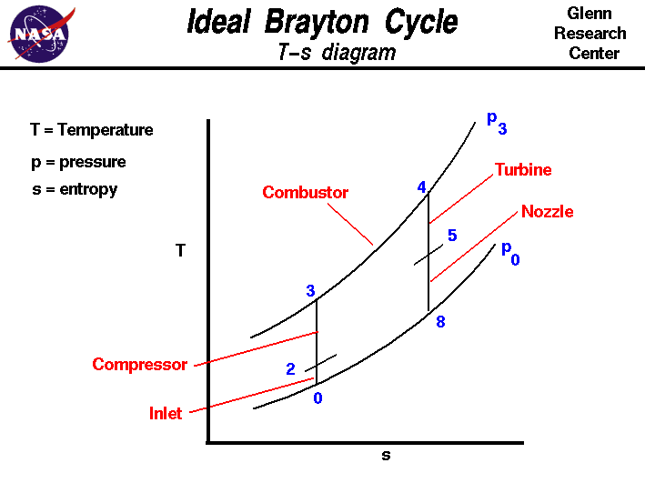
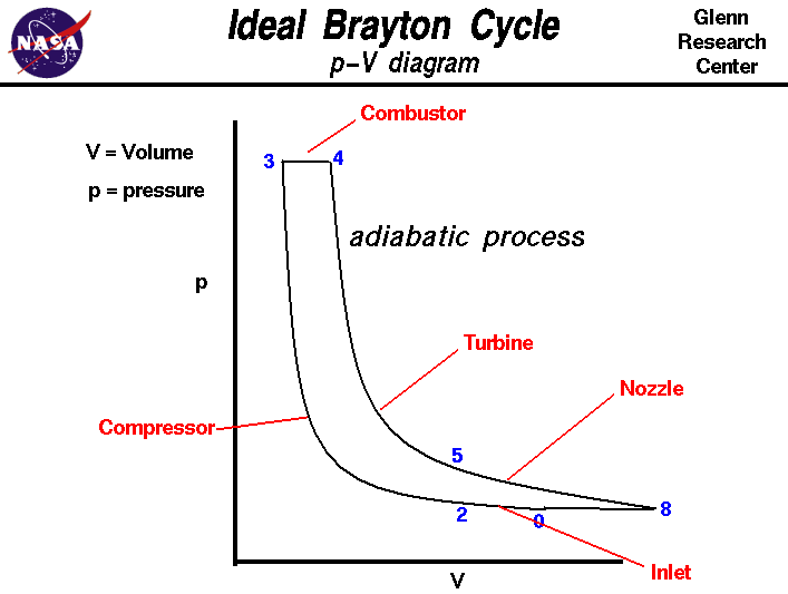
On this page we discuss the Brayton Thermodynamic Cycle which is used in all gas turbine engines. The figure shows a T-s diagram of the Brayton cycle. Using the turbine engine station numbering system, we begin with free stream conditions at station 0. In cruising flight, the inlet slows the air stream as it is brought to the compressor face at station 2. As the flow slows, some of the energy associated with the aircraft velocity increases the static pressure of the air and the flow is compressed. Ideally, the compression is isentropic and the static temperature is also increased as shown on the plot. The compressor does work on the gas and increases the pressure and temperature isentropically to station 3 the compressor exit. Since the compression is ideally isentropic, a vertical line on the T-s diagram describes the process. In reality, the compression is not isentropic and the compression process line leans to the right because of the increase in entropy of the flow. The combustion process in the burner occurs at constant pressure from station 3 to station 4. The temperature increase depends on the type of fuel used and the fuel-air ratio. The hot exhaust is then passed through the power turbine in which work is done by the flow from station 4 to station 5. Because the turbine and compressor are on the same shaft, the work done on the turbine is exactly equal to the work done by the compressor and, ideally, the temperature change is the same. The nozzle then brings the flow isentropically back to free stream pressure from station 5 to station 8. Externally, the flow conditions return to free stream conditions, which completes the cycle. The area under the T-s diagram is proportional to the useful work and thrust generated by the engine. The p-V diagram for the ideal Brayton Cycle is shown here:

Activities:
Guided Tours
Navigation..
- Beginner's Guide Home Page
Source: https://www.grc.nasa.gov/www/k-12/BGP/brayton.html
Posted by: catheycatheylamonse0270859.blogspot.com